
Table of Contents
Epyx original design
Introduction
This is the section where all the original material can be found, including texts, photos and available dimensions. This is a draft where I initially add the content page per page and will somewhat re-arrange for clarity later.
Page 1
The start!
I had started working on the Wasteland Cab but decided to put it on ice because of the lighting colours and difficulty of getting Yellow neon in the size required. My plan is to have two cabs that highlight what I have learned (and push me further out of my comfort zone), one horizontal and one vertical. This is the horizontal cabinet, the Wasteland will eventually be the vertical cabinet. I have scrapped the portable from the build. These things will be staying put and are much smaller than my original behemoth of a cab if I do end up having to move them (at least these will fit through doorways!).
I have started the horizontal first because the colour scheme has readily available lighting and cause Aliens are cool.
I want this cab to be a mix of BYOAC cabs that I have drooled over the last few years. Two that immediately come to mind are Martijn's SF cab and Knievel's Neon mame (copied ad nauseum but I like it!).
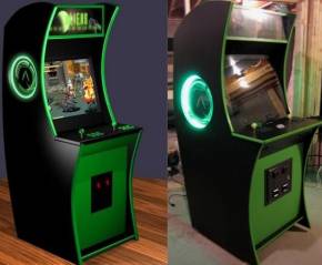
This cab will feature elements I like from both cabs…the lighting and side-work of Neon with the sexy curves of Martijn's cab. Colour scheme will be black with Galaxian green T-Molding. Cost will be kept down because everything on my 1st upright will more or less be transplanted over (at least that was the story I told my wife *cough*)
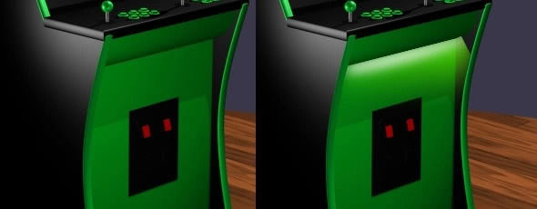
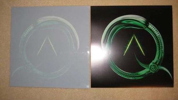
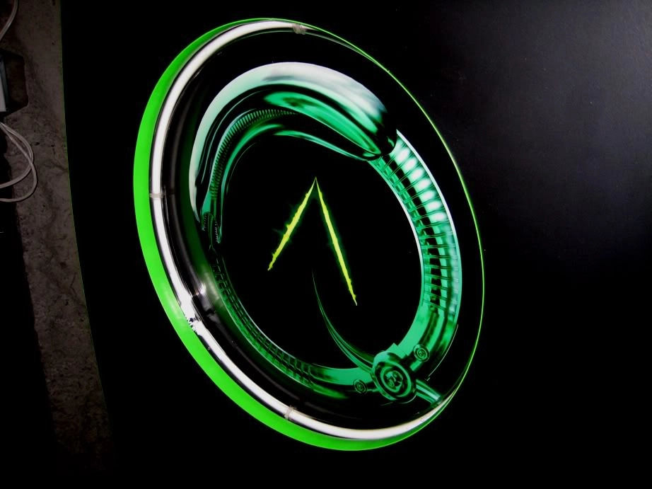
I always liked the cover art on the Alien Quadrilogy box set and felt it would make a pretty nice neon side art. Ond was kind enough to take the small crappy picture I sent him and re-do it (better than the original imo):


Process
Here is the first version of the measurements, which was printed out in 3 angle views (front/side/back) and filled with about 40 additional measurements soon after.
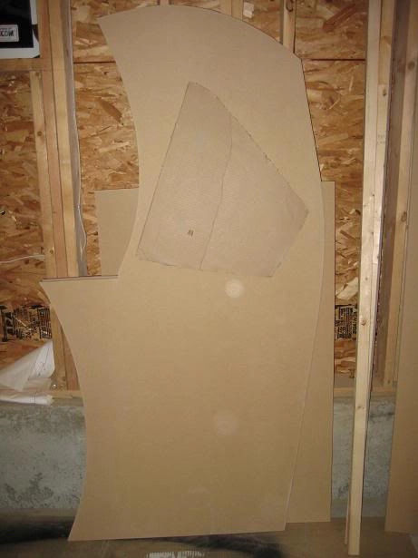
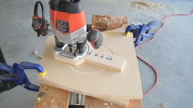
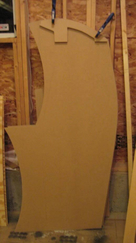
This was then transferred to wood 3/4“ MDF. I created a quick n'dirty cardboard dimensional representation of my 27” WG D9800 monitor to ensure the size works. I used some scrap laminate and my clamps (what can't these things do…) to draw the curves.


I used a large chunk of leftover rectangular laminate…approx 8“ wide by 60” long. You can see this in one of the above pictures. Using clamps I held the back of the curve in place. I would then trace with a pencil along the inner side of the curve. I would start at one end but just a bit ahead of my pencil (maybe 12“) I would place a counterweight like wood etc to push the laminate against the clamps from behind, maintaining the curve.
The picture above shows only a couple of clamps but this picture was before drawing…during drawing I had about 8 clamps forming the backside of the curve.
The actual cutting of the curves was done with my jigsaw (going very slow and steady and set to slight orbital curve). I then sanded just the first piece smooth. The 2nd piece I will route tonight using the first piece as a template with my flush router bit.
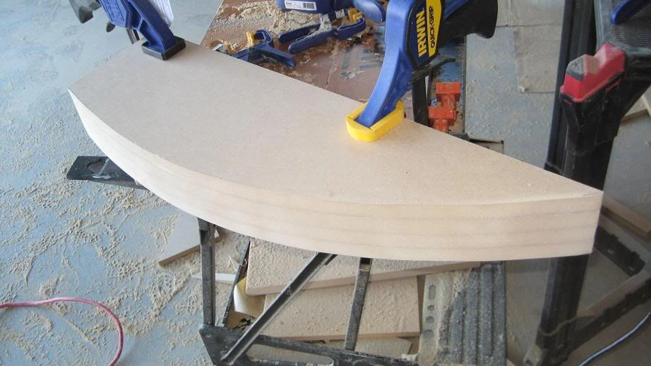
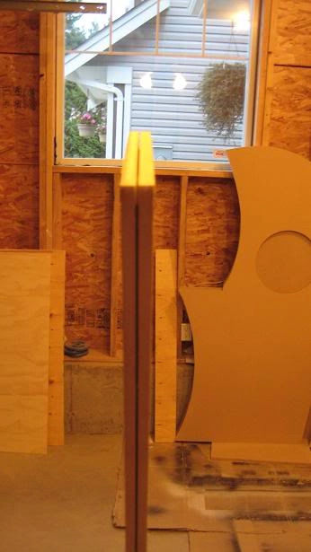
I touched up my pencil lines on the MDF and just went for the curves. I left about 3” that leaves a bit for the bezel and glass and the back panel will be 1/4“ Plywood and the cross bracing I use will sit above and below that portion of the monitor. Here was the final pencil outline I went with:


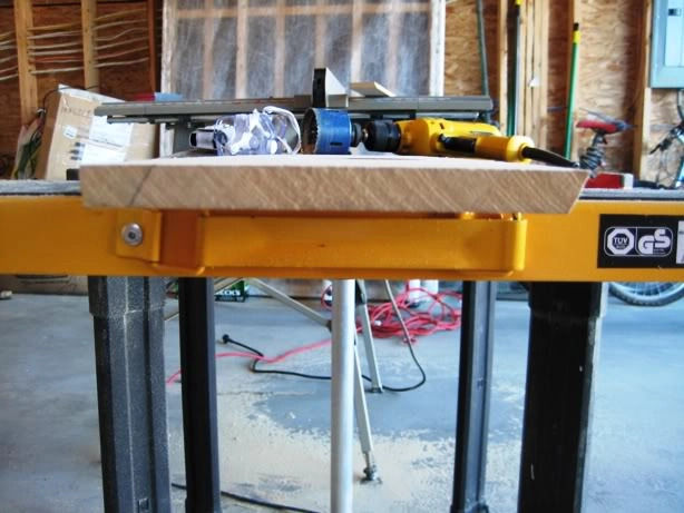
Prepping the first piece on the sanding table for use tomorrow as the template guide for routing both pieces:
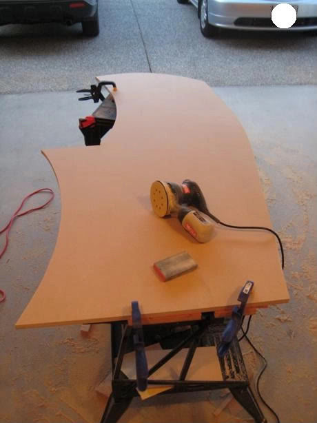
And a final pic before tomorrows routing of the sanded template side with monitor mock up back on:
The top and back will be two pieces of curved plywood. Each piece will sit atop a brace frame that will connect it to the sides. The idea is for a flush outter shell that rides just lower than the Galaxian green T-molding along the edge, maybe 1/8”.
I initially had some thought about portability, and decided what I really wanted was the ability to disassemble the cab if required.
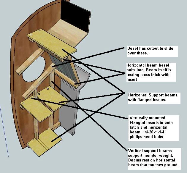
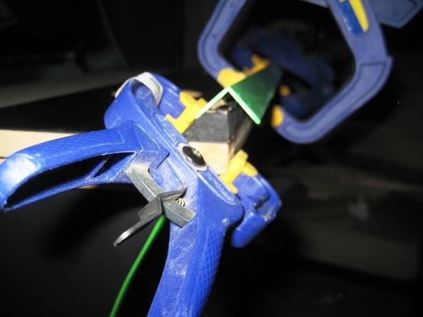
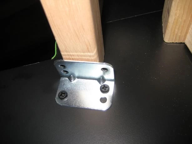
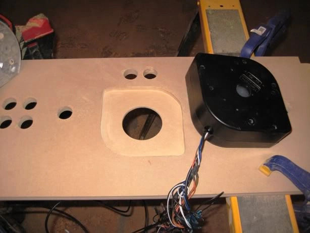
I did a quick mock up to test if I could do a horizontal flanged insert. The idea being three horizontal layers of support beams. Most of the weight in the cab is weight pushing down, not to the side. With this logic as long as the monitor weight is directly support by the ground via support beams I should be able to connect the sides with horizontal beams that use vertically mounted flanged inserts. Mounting the flanged inserts this way ensures they won't get ripped out. The bolt screws through the horizontal beam and then into the cross latch which itself is mounted to the side via wood glue.
To disassemble the cab I would remove the top marquee retainer (also connected via inserts) and remove the marquee picture, marquee light (also on a horizontal board). Then I would remove the monitor and computer and take out the horizontal support beams. Using the inserts I don't have to worry about wearing out screw holes etc.
This picture illustrates the idea:
And here pictures of a mock up to test the idea.


The top and back will be plywood. 1/8“ on the top and 1/4” on the back. I will use one of the existing sides of the cabinet as a template for the curve of the exo-skeleton that the plywood will curve over. The back and top will each have 4 ribs. The outer side ribs of the top portion will connect to the sides of the cab via horizontal flanged inserts (the main horizontal support beams have vertical ones so this should be fine).
The plan for the back is a series of magnets, like a hatch door. I used magnets on my first cab and it worked well so hopefully it works here. Both top and back will have the laminate over the plywood so this should form a smooth matching curved back and top just under the side edges.
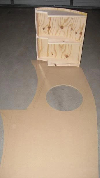
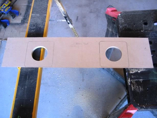
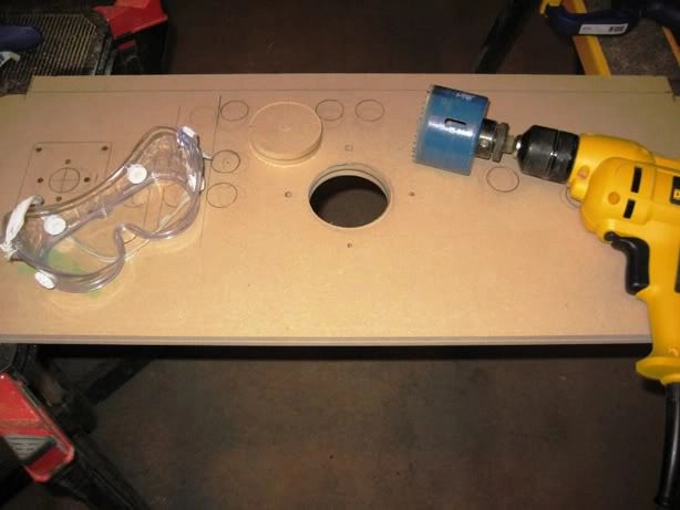
Making a circle jig and the start of the top portion of the cab. The top portion will hold the marquee, lighting and curved plywood (to where it will meet the back panel). The circle jig is nothing fancy compared to some of the ones on here but does the sizes I will require (8“, 10”, 12“, 14.5” and 15“) Over the coming days I will determine if I go with 12”, 14.5“ or 15”:
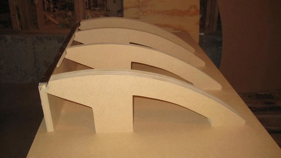
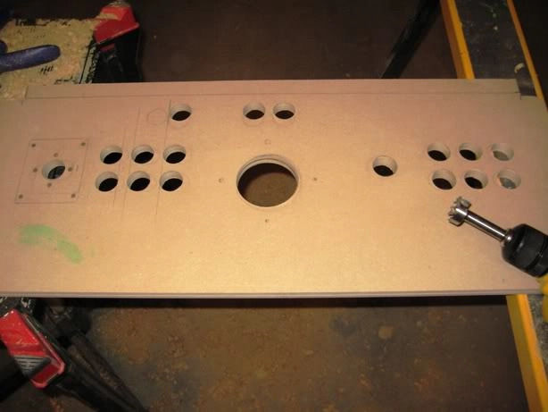
Here are the 6 MDF pieces (4 below but i had 2 more, that will serve as the ribs that hold the plywood on the top and the top marquee retainer/lighting:
Here is the plan:
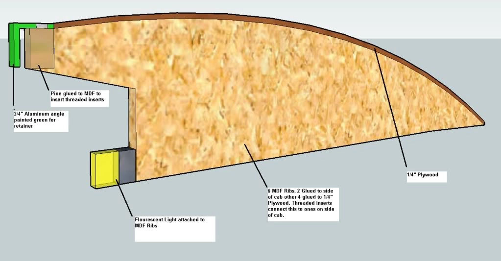
The diagram shows the bottom of the ribs being flat and extended to the bottom of the curve in a straight line. In reality I will make only a 5“ portion flat…the rest will curve along approximately 3” from the top. I have tested the plywood and it curves perfectly (and as Ond mentioned…easily) along the top. Over the next few days I will glue this on once I have everything lined up. Overtop of the plywood will sit the laminate.
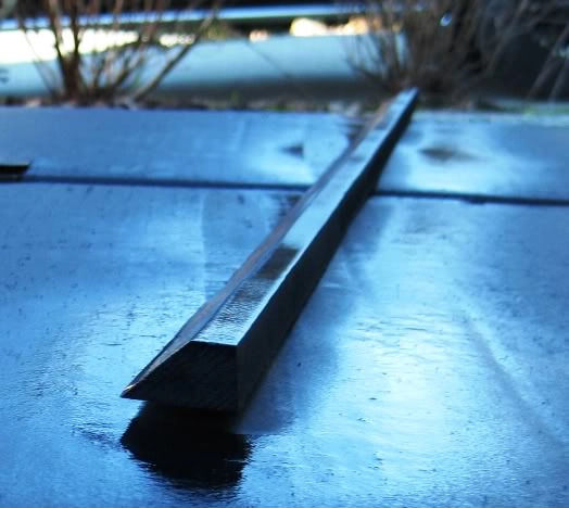
I purchased a 3/4“ aluminum angle which I will paint green and act as the marquee retainer. The top portion as illustrated will be attached to the pine via threaded inserts. 1 rib will be glued to each side of the cab. The other 4 will form the skeleton for the plywood. The outter 2 ribs will be offset from the edge of the plywood by 3/4” so that the 3/4“ plywood overhang will rest flush with the ribs glued to the side. They will also attach via threaded inserts.
Here are some pictures to better show what I will do.
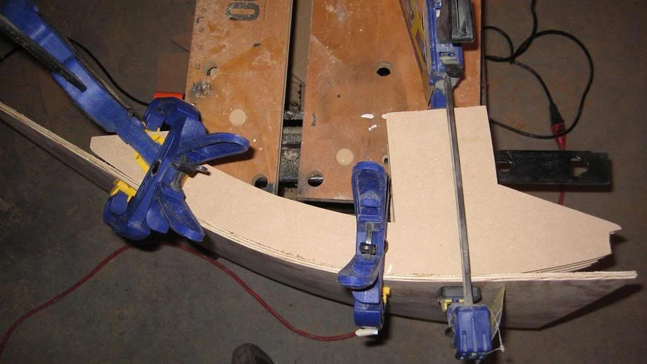
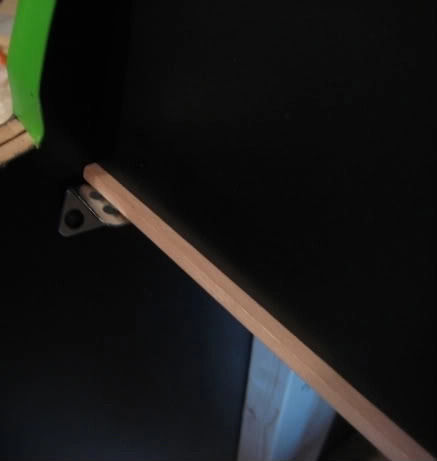
Each side of the cab will have one of the ribs (made of pine or harder wood) connected to it with threaded inserts. The main stress will be downward and the vertical inserts will take the load off the few horizontal ones I use (like these). You can also see on this picture the idea behind the curved skelton. It will continue in a 2nd piece that will curve along the back to the bottom so that what I end up with is a nice curve outlining the cab…no squares here.
Here is a picture of them lined up on a workbench so you can see the approximate spacing. Note they are doubled up on the sides. One piece on the cab side as mentioned and the outmost of the rib set will thread screw to the one on the cab side. The retainer spacing will house a small piece of pine that I will glue on and I have cut it so it is square with the ground.
Here is a front shot to give you an idea of how the retainer will sit. Of course it will be green and will be slightly higher (no pine in there yet):
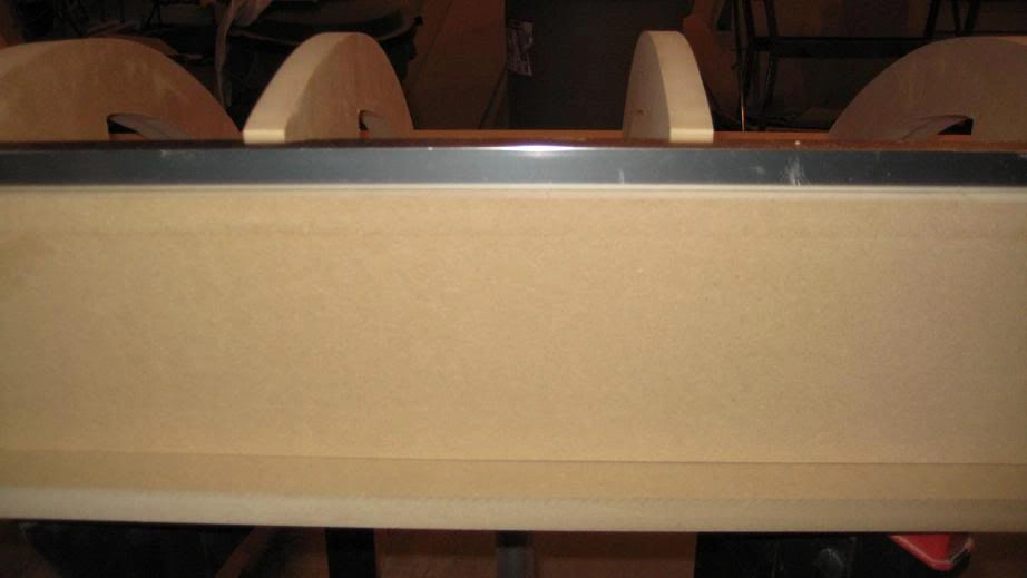
Next, I'm going to finish the retainer portion and mount the pine retainer beam. There will also be a piece of pine that will run along the flat inner portion you see.
Page 2
I had to redo the arches for the curved top in pine as opposed to MDF. It was difficult to set the glue without screws (which kept splitting the MDF, I should have foreseen this). So I switched over the weekend to pine so I can screw through into the pine plus set with glue which worked much, much better.
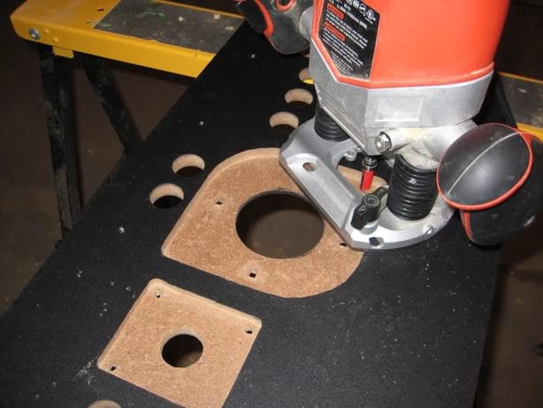
I used 1/4” plywood (birch) as mentioned which kept a very smooth surface on the outside, which I think was key. There were a few minor indentations along the grain which I just filled and sanded smooth. The laminate then applied pretty as long as you wait until both sides have dried fairly well before pressing them together. Then just trimmed with router trim bit running along the 1/4“ border with bottom bearing bit as the ribs prevented routing from the underside with top bearing bit.
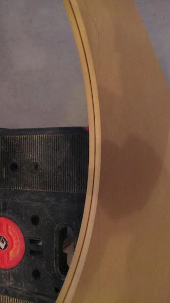
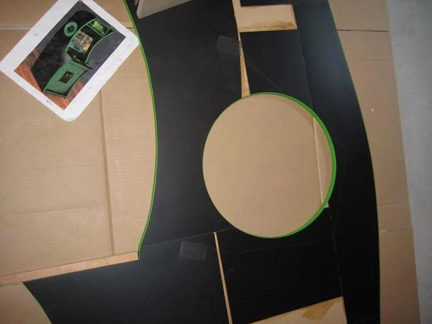
I was originally going to go with 12” side holes but they looked really small traced onto the side of the cab. I figured stability wasn't going to be an issue and since I designed my circle jig to do up to 15“ circles, I'd go for 15”. Used the jig on the first side and then a flush trim bit for the 2nd side. The circle jig was so effortless I encourage anyone/everyone who doesn't have one to take the time (couple hours at most) to make one. Here is a shot of one of the entire sides:


I cut a slot into the center of the hole as I will be running the T-Molding around the hole like I have seen on a few other cabs. I think it will look pretty good when done with the green neon light and artwork and T Molding as a trim:
Here is a shot of the where the top and front meet. I can't wait to see the T-Molding on here:
Next I worked on the ribs of the top of the cab and the curved plywood that would rest on top. My first go at this was pretty disastrous…I had tried gluing the MDF ribs to the plywood but just couldn't get it to set properly and figured I would need some screws as well to assist the clamps due to the bending momentum of the plywood. Well as soon as I thought that my 2nd thought was…DOH…screws will just split the MDF…sure enough the first few split it.
Back to the drawing board and Saturday I decided to use hardwood (pine) instead of MDF for the ribs, this time opting for 3 ribs and enough space on each end for one rib which will be glued to the inner cab sides and fit on like a hat then screw in to connect the two. Here is how it looked turtled on its back:


Here is a shot showing the front of the top with one of the threaded inserts that the top marquee retainer will screw into, ill show this in more detail below:
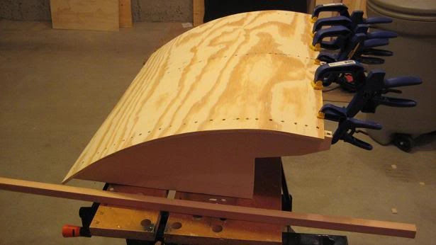
And here is a back view of the top before lamination:
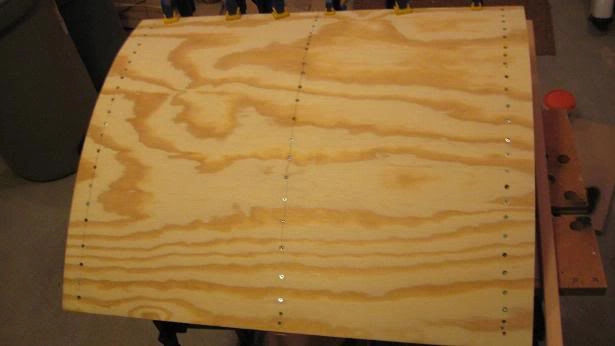
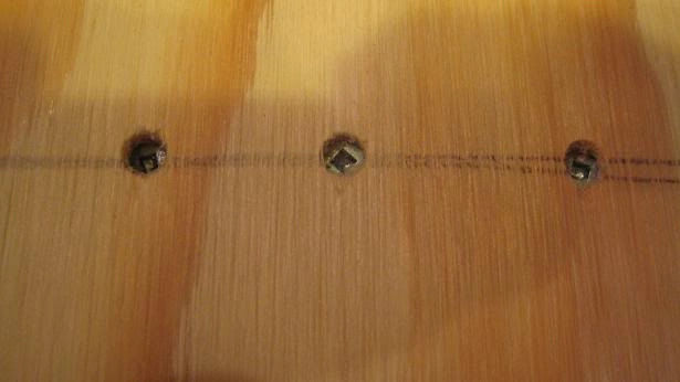
And a closeup of the screws. You can see in this shot they are all countersunk which ensured no contact with the laminate:
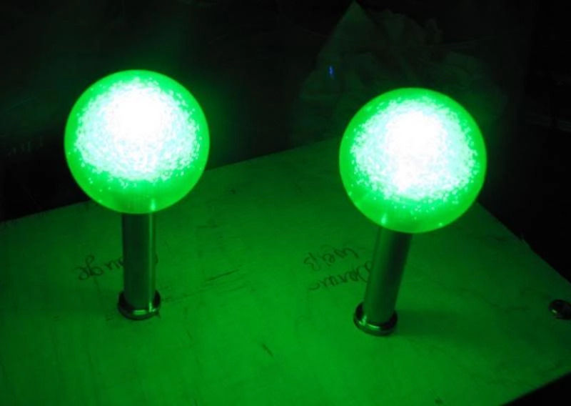
And finally just a quick shot of the T-molding (Galaxian Green). Also in the picture are two of the balltops. I will be getting another pair with leds and hollow shafts for the JLWs which DHL tracking says will be delivered tomorrow. Also in the bottom picture is the colour I will be using for the bottom front of the cabinet, called Fern Green:


I traced out the outline of the top by laying it and rolling it. Then put contact cement on both the top and laminate. I went over the lines on the laminate to ensure coverage. Then I made sure to wait at least 30 mins to let the cement dry on both pieces:


Then I prayed to the 4 winds, Crom and any other deity that would listen and applied the laminate to the top. There isn't a 2nd chance on setting and thankfully it lined up perfectly along the front where I wanted about 2mm of overhang:


Then I gave it a good trim with the router and as mentioned my bottom bearing trim bit which rode the bottom 1/8“ of the 1/4” plywood. This was quick and effortless. Here you can see a shot from the top of the front where the marquee retainer is bolted in. The Retainer and Bolts will be green. I will also laminate the top portion just above the retainer so you won't see the plywood:
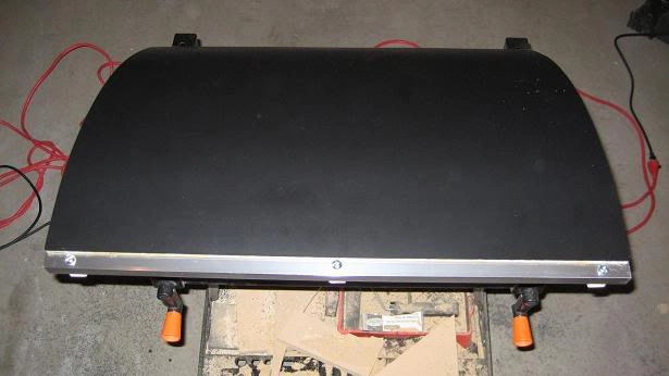
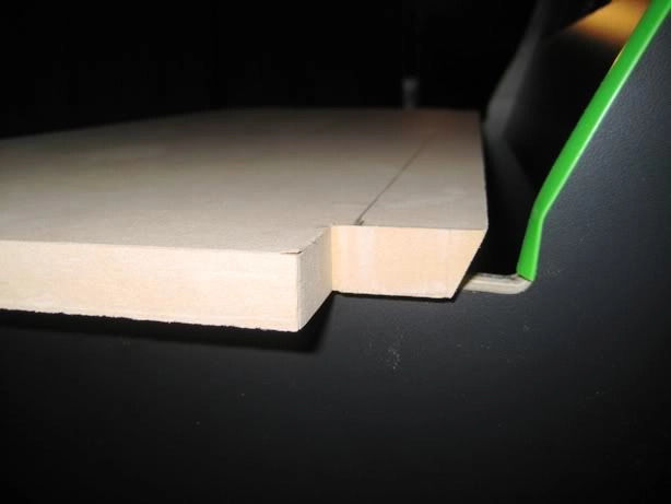
Then I laid it atop one of the side panels to ensure everything including the curves lined up. This turned out perfect and rides just a few mm shy of where the T Molding will run on the side panels along the top and back:
Notice the gap between the side of the cab and the outter rib in the picture below. That is where the a rib will be attached to the side of the cab and the top piece will sit atop and bolt into.


Page 3
The Laminate is indeed the Formica product from Home Depot $60 CAD. It is 1/16“ in thickness and required absolutely no heating to bend it. It took me about 5 hours to do the laminating for just 1 side lol. I have 3 sheets of laminate for figured id use 1 for each side and the leftovers for the inside and 3rd sheet for back and spare for future CPs. Brushed Lepage contact cement onto both sides and separated with sticks to line them up as close as possible:


Here is the outside of side 1 fully laminated before and after side hole was trimmed:


I then laminated the inside which you can see is a patchwork of odds and ends. I put as much towards the center as I could because I will be mounting strips and don't want parts of the strip on laminate and part off:


And here is the outside of side 1 with Galaxian green T Molding along outter slot and inside side hole:


Could add a row of LEDs under the CP area to lit the front coin door panel with a bit of green light:. Would either need a diffuser of some sort or a green cold cathode. I think a small u shaped recess at the bottom of the curve would work best and that way I can slot a G. C cathode in there and drill a hole for the cabling out of sight.
Cold Cathodes are really cheap…a pair like in the picture below run about $10 and they come in various colours. Here is what the green cold cathode I will be using looks like lit if you are curious:


Here are the 3 corners of the cab in closer detail for those who have been curious.
Here are two angles of the CP Corner. In the first picture a side shot of the CP corner where T mold/cut and laminate meet. In the 2nd picture you can see the beauty of using 5/8” MDF is that once the glue is added to the Laminate you get a perfect end to end flush with T Molding applied:


Here is the top corner of the cab:


And finally the bottom corner. Again two views:


Page 4
Current list of costs for those who are curious:
(date: Oct 20, 2009)
Home Depot
- Wood - $90
- Paint - $27
- Caster Wheels - $36
- Laminate - $180
- Misc - $80
NCIX
- Lighting Cathodes+Mods - $50
Ultimarc
- JLW w/Balltops - $50
GGG
- 1 x LED-Wiz™ 32-port USB Lighting and Output Controller
- Device Number: 1 (Use if FIRST or ONLY device o $44.95
- 1 x TokenTop™ Premium Spinner Knob
- Rubber Color: Black
- Token Inlay: BYOAC Logo - Brass $22.95
- 12 x NovaGem™ Lightable Horizontal Pushbutton
- Microswitch: Micro-Leaf™
- Color: Green $97.20
- 1 x Electric ICE™ RGB Trackball Lighting Upgrade Kit V2.0
- Trackball Size: 3 inch
- Lighting Option: RGB Overdrive™ $36.95
- Thorsten's Led Balltops+ Hollow Shafts - $42
Total = Ouch…so much for the cheap upgrade lol but it's done the way I want it.
Ordered the side art from a local sign shop called FastSigns. Side art is going to be printed to back lit vinyl at 16“x16” with the artwork centered to appear centered in the circular side holes. Can't wait to see these babies lit up. Should be ready by Friday, just in time for the weekend woodworking. Need to wait to confirm exact dimensions for Marquee but at this point looks like 26.5“x7”.
They have several constantly lit displays…it's professional back lit vinyl for back lit mounted signs. The stuff is night and day compared to what I got from Staples for my Marquee…It is thick, resistant to fading and designed for lighting specifically.
It's actually called “backlit film”. It almost feels like thick cellophane if that makes sense. They assured me it's heat resistant, wont fade etc. Here is a link
That is just their web example in the showroom they had at least 12 and one that caught my eye was colour rich and it really popped with flourescent backlighting…they had others with LED backlighting so you could see the difference. I was really impressed with the product.
Their products are stacked as follows: lighting then the sandwiched film between glass/plexi.
And yes, it will be sandwiched between plexi just like other marquees.
Product name is “Backlit Poly Film” specific design for Light Boxes. The thickness is 1 mil. This is a non-adhesive backlit film.
The side art is two pieces and each piece is 16×16“ and they are $30 per piece. I would imagine a Marquee would be in the $20 - $24 range based on the square inches. That isn't too bad and no shipping.
My plan is to have it sandwiched in plexi (the side art) with just the circular inner portion showing in the side holes…the plexi will be backed by hardboard coated in aluminum foil or something even more reflective with a gap for the cold cathode tubes.
I will be going with my own lighting (for the side art illumination) via the Cold Cathode which is a form of neon light as opposed to LED light. For the marquee I will likely go with either a white cold cathode or LED.
Thorsten just sent me notice of a pic of my balltops all lit up and ready (they are now enroute) on his gallery:
Picture of the two pieces of side art…both backlit poly film…one is turned so you can see the film material from the back:
Page 5
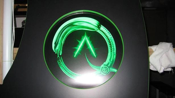
Picture of the side art taped up from behind and unlit on the second side of the cab which I finished a few days ago:
And a few lit pictures…I just dangled the light from behind…no diffusion yet which I will do with a back layer of frosted plexi (art will be sandwiched…reg plexi…art…frosted…cathodes…foil and backing). The pictures don't capture how great this looks even with it not being diffused. For one the art is clear and not shadowy looking and the black surrounding and in between the graphic doesn't have a green smear:
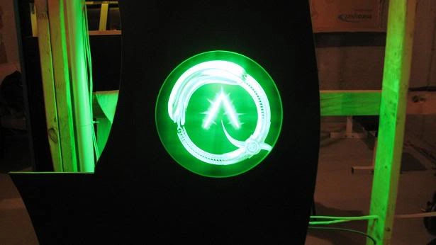


The plan is to diffuse the light with frosted plexi in behind the side art. As above the neon rings are no longer being manufactured so I am searching the Internets for any and all alternatives…worst case I leave it backlit which still looks friggin unreal in person and only that much better once it's diffused im sure.
The Marquee was $28 and that includes lamination. I wouldn't think its necessary, I just did it to eliminate any possibility of ink transferring to plexi over time.
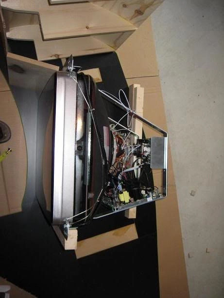
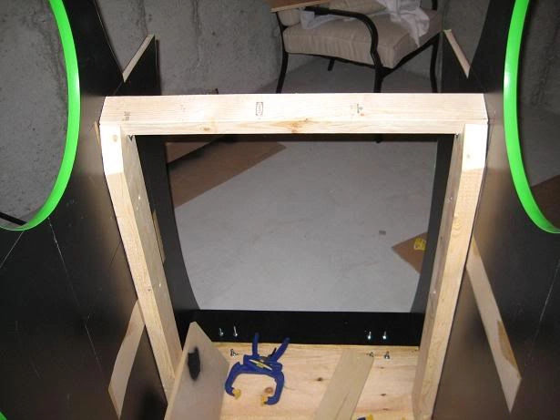
The first thing I did was shlep the 27” WG D9800 from the big cab to one of the side panels for measuring. Top view of the back:
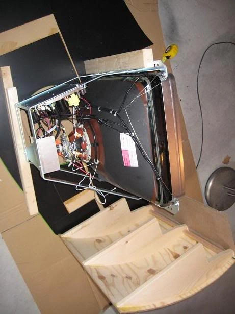
Top side view of the front angle of the monitor. I placed the beam I will use to rest the bottom of the monitor on underneath the bottom support bracket:
I traced the bottom beam to use as a measurement for the 2x4s. You can see my trusty colour print out of Ond's render, which I use constantly to consult the design:
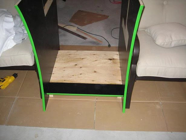
Here I am test fitting the bottom:
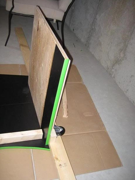
And finally once I was happy with everything, I raised both sides and put the bottom in place, double measured everything and then permanently attached the base:
Then I worked on the monitor mount:
Once I was happy with the monitor mount and test fitted the roof. Also, no fears that is just a piece of cardboard (8.5“ x 26.5”) to test the marquee dimenions.  , you have to love clamps eh?:


Side Bracings permanently mounted after careful measurements:


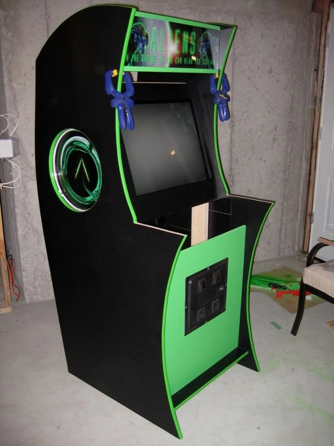
And finally I connected the roof to the cab. Here are various angles of the cab with the roof and monitor mount in place:


The lamination definitely adds to the aesthetics. With a regular paint job you tend to second guess a lot…is it smooth enough? One more sanding? Another coat? It sure is nice with laminate to just glue it on and trim and then forget about it. My challenge will be in painting the green areas so they at least approximate a laminated finish.
I'm worried that no matter how well I paint those green areas, they are going to stick out beside the laminate. Plan is a high gloss paint and then take time and let it cure, sand, paint, cure, sand, paint, repeat. I think the paint will look ok as long as you don't rush it.
Page 6
How do you plan on handling the back? Did I miss that somewhere in the thread? I'm planning a curved door for mine so I'm interested to hear how you are approaching yours.
The back will be similarly curved but I will do that in 2 parts…a permanent top half and a removable bottom half for the computer. The top half will have an opening but only for a UV Green 120mm fan. The back straightens out at the midway mark going down so the removable bottom panel will not be curved, making it easier to remove.
So picture a similar curve extending from where the top ends down to the midway point where the back straightens, with a green UV fan. I want to get a custom Aliens picture laser cut for it.
Oh and to get the curved shape, same idea that worked well for me for the top…curved ribs that I have already put aside for the sides and some mid structure to attach the curve to. All of them were template routed based on the back curve. so it will be a flush mount riding just shy of the t-molding.
The top stayed pretty rigid when not attached and I have been using threaded inserts. So each side rib has a three threaded inserts. The outermost ribs on the roof itself have lined up threaded inserts…then I just screw the bolt in to join them together.
It is completely solid and won't move on its own or when joined to the cab. I did the top and bottom first for this very reason…my first cab different parts of the cab weren't the same width…this time I wanted 26.5“ from top to bottom with not even 1/16” variance…so far so good.
I installed the upper monitor brace and test fitted my WG D9800 monitor. I have included some pictures of the bolt holes and placement on the beams. I ended up cutting 4 notches to clear the bolts. Tomorrow the fun begins, cutting the various panels for the front, the bezel, speaker and bottomr marquee retainer shelf and the coin door, CP and piece that joins the two. I will also close in the light chamber of the marquee area.
The width of the bezel area is 26.5“, leaving 2-5/8” from edge of viewable screen to side of cab on each side.


Updated the marquee and placed the order. For the price, im happy with it (even though it has “characters”! and the caption is cheesy…but I like frommage!) and not like I can't take it out and change/update it later. This is an update to the earlier one on page 1 of this thread. 26.5' x 8.5“. Here is the proof that FastSigns sent me (White border is just from the proof sheet and will not be on final print):

Page 7
Here is the marquee alongside the sideart. I did a mockup with the marquee illuminated and it looked as good as I had hoped it would.
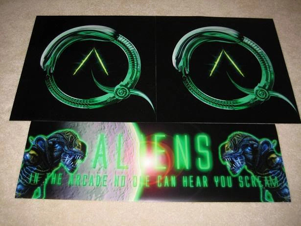
Table with the goodies. RGB 3” Trackball Upgrade Kit, LEDWiz, 12 Green Novagems, 12 Microleaf switches, 2 Modded J Sticks (ultimarcs with Thorstens' LED mod), and the BYOAC prize unopened going to the Twin Cobra winner:
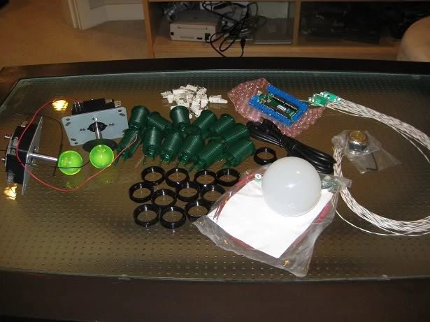
As you can see, true to Randy's statement the Green Novagems are not as translucent as the other NovaGems…but you know this is actually not a bad thing imo:
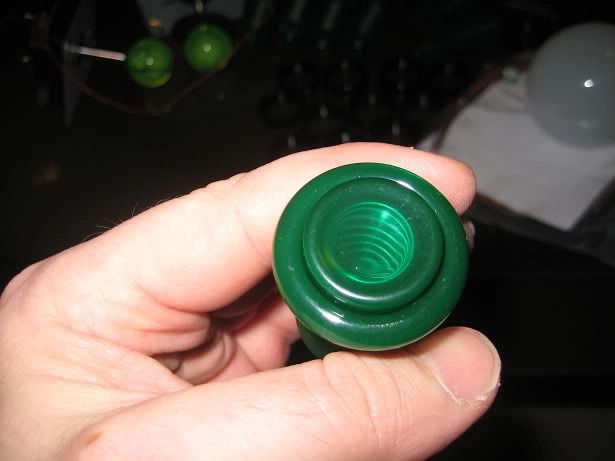
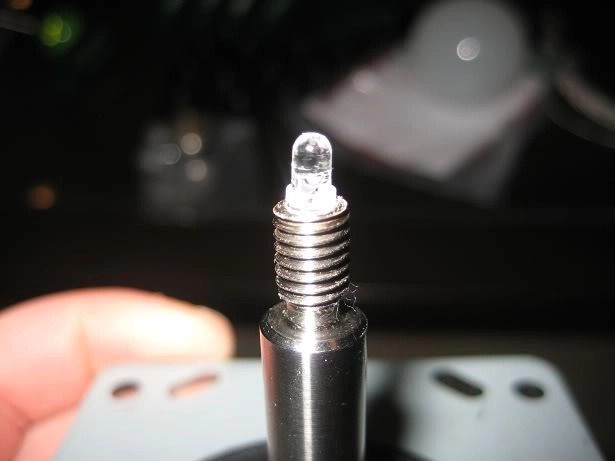
Here is a closeup for those interested showing a hollowed shaft courtesy of Thorsten:
And a pic of the led mounted at the top before screwing on the drilled out balltop:
I also got the monitor through X Gaming's Ebay listing…was $349.99 plus shipping ($99) so $449 (USD) total.
I got the coin door done for the cabinet. I will be going one shade darker on the coin door because the hammered paint I had originally used for my previous cabinet is a bit on the gray/black side.
CP board below hasn't been trimmed yet and is shown just as a placeholder.
The paint was a pleasure to work with and rolled on very nicely and quick to dry. I Put on two coats and will be sanding and putting on a 3rd tomorrow:


I also organized all the cabinet parts and forgot to mention these arrived about 8 weeks ago:
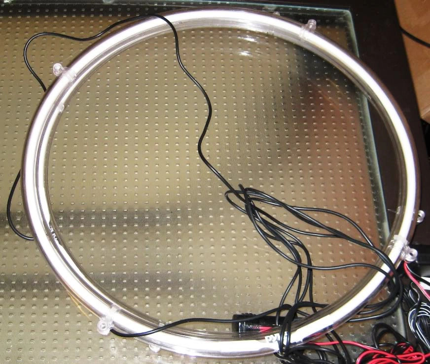
They are 15“ Neon Green speaker rings…ordered from likely the last place on the planet to carry them :) (Thanks again Rablack97!)
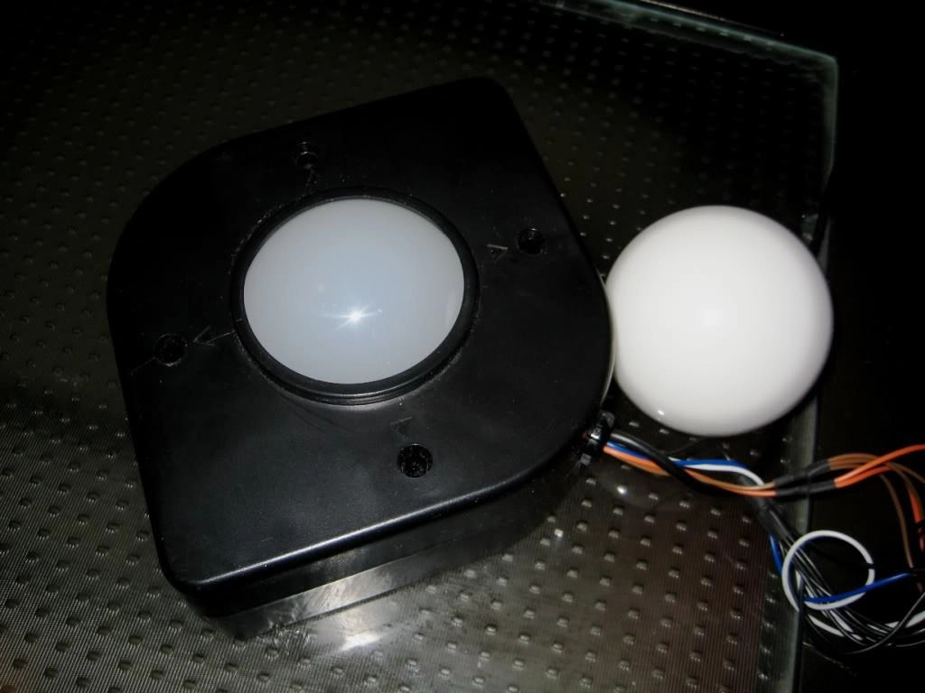
Also swapped the standard white 3” trackball from my Xgaming trackball with Randy's 3“ Electric Ice trackball.
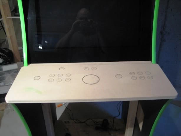
My CP is will be based on the X-Arcade Tankstick…albeit with only 6 buttons, not 8. Here is a picture of the X-Arcade panel sitting on top of my CP so you can see the scale of my CP. As you can see there is plenty of room for the trackball. Note the side shot for depth ;) I will also add a spinner. By going down to 6 buttons I can re-jig it to ensure it doesn't look too cluttered. Either way I will make sure to balance aesthetics with functionality…yes it will have both a spinner and trackball but I think I can pull it off without it looking “too” Frankenpanelish :


Page 8
As shown previously, I have 12 of the Green LED Novagems, 2 green and LED illuminated JLW Joysticks, a green RGB trackball but my Turbo Twist 2 was blue (Big Blue knob) so I gave it a coat of UV green:


t's a UV paint so will glow a nice neon green when lit with a blacklight. I will have a blacklight just under the marquee. I can't wait to see these all lit up against a nice pure black CP…I think the pure black will contrast nicely against the lighting…artwork on the CP would be too much.
Painting was done in 2 passes…first 2 coats were straight neon green for a base…then a UV reactive clear (blacklit neon green) coating overtop.
UV Product: http://www.xoxide.com/greenuvpaint.html
- Some sort of half cut PVC pipe? Would need to be 8” or so in diameter to get the right angle
- Woodworking wizardry to have strips of MDF cut to form the semi circle required
Any other ideas?
Maybe benderboard. Can be a bendable plywood made flexible enough to roll up like a poster or an MDF material with pre cut kerfs. I've heard kerfing can telegraph through veneer, (but maybe not laminate??)
Here is some related info from http://www.joewoodworker.com/veneering/vacuumforming.htm
"What is the tightest curve I can pull in a vacuum bag?"Tighter curves are made by using a thinner substrate. These are the bending radius limits, costs and sources for four kinds of thin ply I have used.5.2mm Luan plywood with one face sanded off $12 Most large hardware stores MIN RADIUS: 4.5 inches 1/8” Whacky Wood Three ply Luan/aspen $35 www.boulterplywood.com MIN RADIUS: 3 inches 1/8” Birch Bending plywood (two ply) $35 www.theworkbench.com www.boulterplywood.com MIN RADIUS:1.5 inches Birch Aircraft Plywood 1.5mm (1/16”) $90 www.wicksaircraft.com MIN RADIUS: ¾” inch
or maybe a thin sheet of frosted (sanded?) acrylic backlit green with the Alien's name etched into it.
I used 3mm plywood and it bends very easy and should bend even more if steamed or even heated. 3mm Hardboard would be even better for you as you don't need anything structurally strong.
An alternative would be to use acrylic or lexan. Would be easier bend over a curve.
⇒ Some good links. I had thought of trying to find some bendable MDF locally…I wonder if routing MDF would produce similar results? IE routing strips along the 3/4“ mdf to within 1/4” of the bottom…would that allow it bend similarly or would it just crack?
⇒ The vacuum option is pretty cool ill have to read that more at lunch…and the acrylic is another possibility.
⇒ I actually read that thread but haven't found a place (yet) here in Vancouver that sells it…I know I can order it online and will if it is my last option. It gave me the thought of routing regular MDF but I think the bendable stuff has a different surface to prevent if from easily splitting?
⇒ Either way…Ill leave it for last so whatever I end up with looks good. Ill have some updates of the marquee, sideart and bezel hopefully by this weekend. I aim to have the cab done by the 21st as my buddy and I are having a birthday bash (hes 19th and im 21st) and want the cab there to play on with our other friends.
Today I mounted my side-art sandwiches ala the Knievel method. Sandwich consists of the 15“ Neon Ring, Plexi, artwork, hardboard backing. I also completed the first coat of the Marquee retainers and couldn't resist putting them up to see what it will look like. I can't wait to see these neon rings in action…right now they are still connected to a car lighter but once I have the computer in the cab I will connect them to the PS.


The original plan was to back light the artwork as well but given the space between the monitor sides opted to go just for the lighting of the ring…completely negating the point of making them backlit in the first place.
I have 2 cathodes for this purpose…maybe even a slit cut in the hardboard so the cathode only lights up the middle where the two lines are…that would look good and wouldn't be drowned out by the neon rings which is what I think you were getting at as well.
Managed to finish the bezel today.
I used 1/2” MDF. Bezel was cut to 26.5“ x 24”. I used my router to route the inner portion of the bezel, running along clamped straight edges. Once cut, I painted the inner edge so it would match the laminate I put on after.
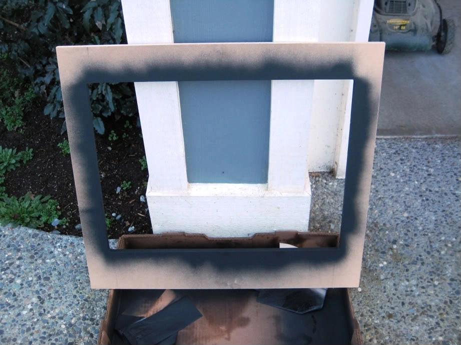
Once the 3 coatings had dried I traced out the bezel on the back of the laminate and then applied glue to both the mdf and the underside of the laminate. I let it dry for about 20 minutes before joining and trimming the laminate.


Once the laminate was trimmed, I taped it up and added another 2 coatings of black to the inner portion of the bezel.
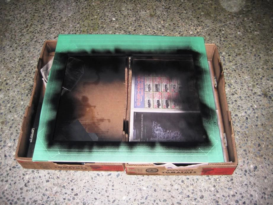
Once that dried I did a test fitting. I like the results and it's nice to see these smaller laminated pieces coming together as it really showcases the advantages of laminate imo.


And finally a shot to update the comparison vs render:
I use Lepage's blue contact cement from Home Depot to laminate the cabinet…it looks like the alien slop but spreads on super easy with a disposable paint brush. It also dries quickly but not too quickly…in other words it gives you enough time to apply glue on both sides before joining (15 to 20 mins).
I began work on my speaker shelf which will also have the bottom portion of the marquee retainer attached. The bottom retainer is permanent unlike the top which can be screwed off as shown earlier in the thread. To get the angle right I created an angled cut which will attach to the speaker shelf so that the retainer angles up to the top portion of the retainer. The bottom retainer will be glued on to the laminate (shown later below):
I also used my table saw to cut an angle on the edge that will sit on the angled bezel so it will be flush:
And drilled 2 speaker holes over which will sit two speaker covers:
Next step was to laminate the bottom of the shelf that will face the CP. I glued both sides. You may have seen it earlier in my thread or on other threads but a great way to line up your laminate and wood is to use small dowels. I used 1/4“ offcuts.


I then flush trimmed the speaker holes:


After this I test fitted the shelf and did the same angled cuts on the CP to allow it to sit flush with the Bezel. I will finish the CP tomorrow or over the next few days and will angle the corners slightly so they aren't too squared off:
Note there is just enough space between the edge of the cab and the CP for the black T molding of the CP to fit.


The bezel will be covered with slightly tinted glass and I will likely have to take a bit extra off of the CP to have it rest on the glass:


Page 9
I think I will also place the monitor's controls under the CP so I can get at it easily to degauss and change other settings.
I got really lucky at a plastic shop yesterday. They had a 1/4” 30“x30” smoked plexi offcut in excellent condition for $5. I figured I would finish the bezel and mount the speaker shelf for the goal of mounting the plexi.
I started with the speaker shelf which up to now has been hanging with clamps and mounted it. As mentioned before the marquee is removed via the top retainer which is connected via 3 bolts.
After mounting the speaker shelf I measured up the distance from where the speaker shelf touches the bezel down to the bottom of the bezel…this ended up being 26.5“ inner cab width by 22 1/4” in length.
I clamped the 30“ x 30” plexi between to pieces of MDF…one piece was a template I cut as I did not want to use my actual bezel and risk scratching it… the template matched the measurements above. I then flush trimmed the plexi. If you want my 2 cents…don't waste your time scoring plexi…it is too prone to you running off the line and you risk scratching your investment…use a flush trim bit and you are good to go. I have zero melting as I maintained a decent clip and ensured I let my bit cool down each pass (each side).
A quick shot for those who are curious how I handled the bottom retainer. You can see the angled piece of wood glued to the speaker shelf on which the bottom retainer is in turn glued:
o keep the bezel in place I use an L shaped piece of pine from Home dept that sits atop two L braces mounted to the side of the cab. The bezel and the retainer will rest on it. A bolt is put in place behind the pine to keep it in place…pictures below:
Here you can see there is exactly 1/4“ of the L Shape sticking out beyond the bezel…perfect fit for the 1/4” plexi! (EDIT: Now using 1/4“ glass).
I then added the smokey plexi and voila a perfect fit. Speakers will be covered as I am still working on them:


I then realized my CP was cut to not take into account plexi over the bezel…ooops…no big deal. I throw it on the table saw and do another 1/4” angle cut so it rests on the plexi flush. I also cut the T mold slot and rounded the edges. Lastly, I used my X arcade to template sketch the buttons (6 each player), trackball, p1/p2 and Spinner (to left of p1/p2):
First few tests of the curved piece worked fine. To create my own bendable MDF I have been cutting slots to within 3/16“ down, spaced 3/4” apart on 3/4“ MDF. I will then put glue in the slots and mold the curve. Ill document this step in closer detail.
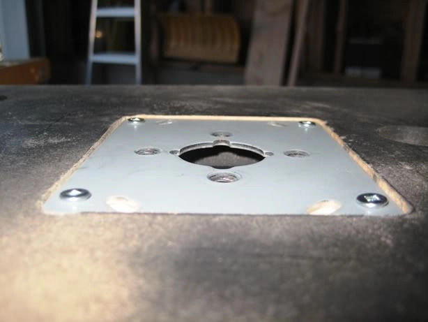
Got in a few hours last night and decided to document the process of flush mounting a trackball installation (Betson/Xgaming) without a mounting plate for those interested. Working on the CP is always the most fun for me because it usually signifies you are down the final stretch. I will hold off on wiring until the rest of the cab is complete but that shouldn't be too much longer.
With the Alien cab I am going for a 6 button layout with trackball and spinner. I like the Capcom 6 button default layout and used my X gaming Tankstick as the template. Only thing I did a bit different is push the buttons and joy for each player out by about 1/2” from the trackball center and added a spinner above the player 1 button set.
I started with my 2 7/8“ hole saw bit for the X Gaming trackball I use. This trackball is essentially a Betson trackball and already comes mod ready with a hole at the bottom for lighting. It is a trackball that feels very comfortable and is one of the few X Gaming peripherals I have no trouble recommending as its a user friendly plug and play device (USB) that feels like the trackballs I remember:
I then drilled the button holes (1 1/8” forstner bit) and joystick/trackball holes (1 1/8“ forstner bit). Everything will be top and flush mounted so the laminate will cover all bolts including the trackball. The joysticks will be top mounted using FrancoB's technique as they are JLWs:
Next step was to place the trackball through the hole and line it up for tracing the part that will get recess routed:
After tracing the mount I went back to my X Gaming CP to set the depth of my router. Both CP's are 5/8”. I prefer this size for a CP when using laminate as it's easy have the T molding cover flush the edge of the laminate. Using 5/8“ CP I will route the Trackball recess to 1/4” of MDF left:
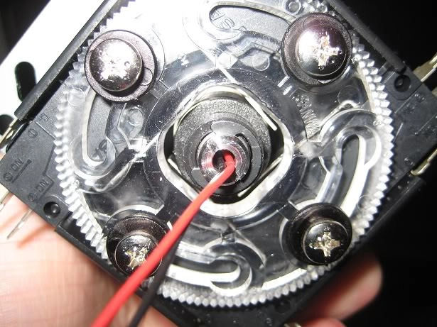
I then route the Trackball recess, note the mod friendly hole at the bottom for RGB lighting (Betson's have these too):
Next up is drilling the bolt holes to hold the trackball. Rather than eyeballing I just drill through the holes with the trackball in place:


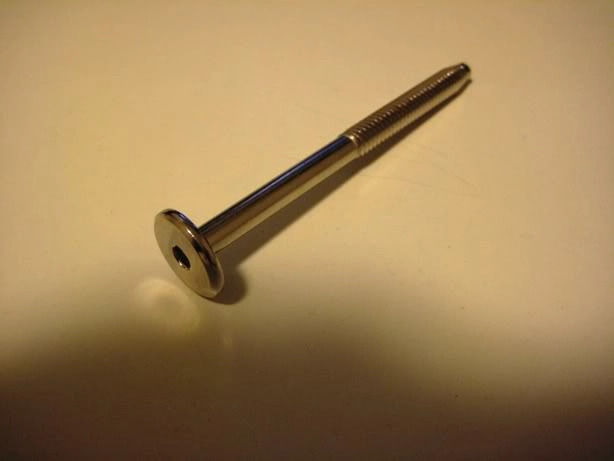
For Trackball bolts (to replace ones it normally uses) I found these hex bolts which have a flat head of about 1/16“:
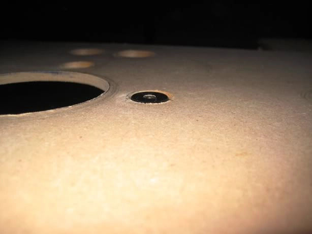
I then placed the bolt in the holes I had drilled and traced around the head:
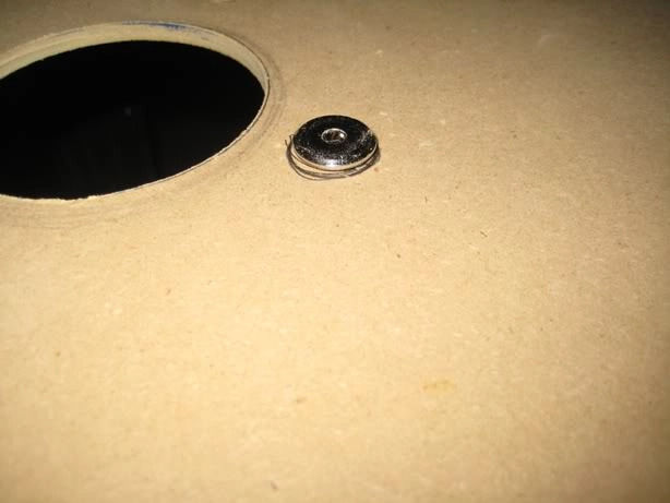
Then routed out 1/16” of MDF for a flush fit. I left a bit of space so that once the CP is ready to get laminated I will glue the bolts in place:
I completed the CP. This involved routing out the Sanwa JLWs for flush top mounting. Again the idea is to have everything under the laminate…no bolts.
Before routing the joystick top mounts I needed to route out the laminate as the joysticks will be using 1 1/8“ holes (could go smaller). To route the laminate with no chipping I generally start all button holes with a 5/8” spade bit..that way any chips or splits are routed out with the flush trim bit after:


Next I routed the top portion of the Sanwa mount (Thanks to Franco B for his excellent tutorial on top mounting Sanwa sticks!):


Perfectly flush. I used 6-32 flat head bolts which barely add any height to the profile…less than 1mm:
I then mounted the XGaming Betson clone with RGB ball from GGG and the modded Sanwas:


Man to say I can't wait to play is a massive understatement, but I promised myself…patience and attention to detail. Speaking of detail, you will notice a missing Green Novagem button. /SIGH…I had it for colour matching…and lost it…its somewhere in my house I hope!:


Here is the green T molding which looks like the clear winner!


The sides are being lit in two ways…first through the Green Neon speaker ring (15“) and from behind (art is backlit film)…the behind lighting will be subtle so it only illuminates the crevasse at the center of the picture.
I think the theme will be better served with lighting from the sources mentioned above so no lighting underneath the CP.
Page 10
I will try to diffuse the light differently from those original pics and limit it to just the crevasse. In the pics the light was non-diffused and was illuminating the entire circle from behind. Hopefully limiting it to just a slit opening behind the crevasse and diffusing it will help. If not, I will just go with the Neon rings.
You know I was actually thinking about going black under the CP as it would allow me to laminate…here is why this might work better. The curved MDF I have been testing using slits cut every 1/2” to within 1/8“ depth, bends fine but reveals the ribs from behind in the light…ie the creases when bending. This would likely still be visible painted.
Going with black laminate will cover those creases and also allow me to embed two black USB circular ports just under the lip. So agreed, black just might work better on more than one front.
I purchased a 26.5”x22 1/4“ piece of smoked glass to replace the plexi I was using…main reason is the larger plexi was a static magnet. The glass fit like a glove and looks smokin (excuse the bad 3am pun!).
First thing I noticed in my mailbox on the way home were the added parts I had ordered.
Speaker Mounts:


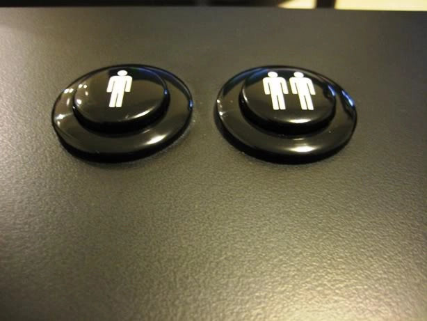
And these black convex player 1/2 black with white to replace the traditional white with black…I think it looks much better:
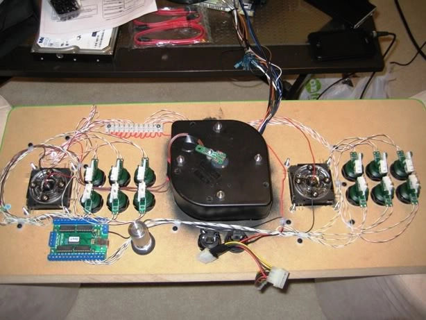
Objective since it was too late to work in the garage cutting, was to complete at least the LED Wiz wiring.
First up was the RGB drive and mounting it on the XGaming Betson clone I have. I am not sure about the actual Betson's…but the XGaming one has a screw sized hole right near the bottom trackball hole, as if intended for the RGB kit:


I then connected the Novagems to the buttons. Here is the spare IL translucent green after I drilled it (I ordered replacements from RandyT but will just keep those as spares when they arrive):


Here is the wiring complete for the LED Wiz…the mini rats nest on the top left will be organized further…getting tired! You can see to the right of the nest a euro terminal block that is feeding the 5 volts for the Lighting. The 5v runs to a hacked molex plug which will hang beneath the CP.
Here is the CP with new Player 1 /2 buttons lit with the lights in the room still on. The Trackball is RGB but I just set it to Green for this pic:
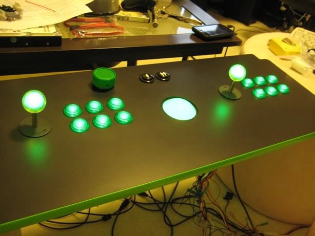
And finally with the lights off:
I am really pleased with the lighting…damn those Novagems are bright when viewed top down!
This panel will include USB and some other ports/buttons.
I worked on the panel between the coin door and CP. This panel has 2 Neutrik USB ports on the left and 5 buttons on the right…I know…why 5 buttons? Well they aren't all going to be buttons. Only 3 will be functional as buttons…the far left 2 will be mouse buttons and the far right will be the power (Green Novagem…lit when powered). The other 2 will have button covers but contain Volume adjustment and the last one a headphone jack. Once I have finished these mods I will post the process as well.
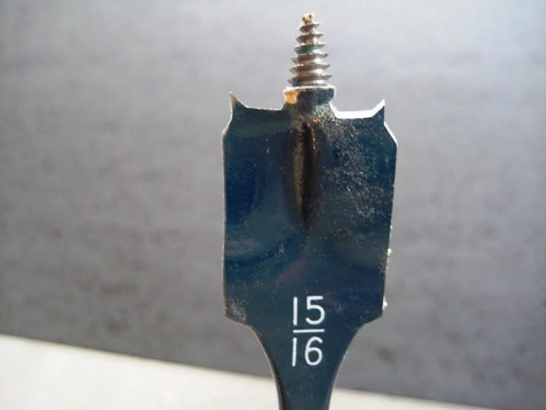
So first up the panel. I used a 15/16 spade bit which is a perfect fit for the Neutrik USB ports if anyone wants them mounted perfectly:
First I lined up the buttons and adapters where I wanted them…this was about 2/3 up so I can reach my hand down and around the lip for power and mouse buttons.
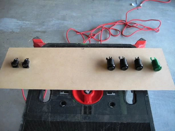
Next up was the lamination. Again I use my small cuts to line up the laminate before joining and trimming:


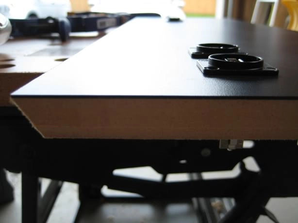
Both the top and bottom of the panel were angle cut to rest flush on the CP and Coin door:
Here is the panel attached with the neon rings lit up. I will still be cutting slits to light the crevasse as my test shows its dark enough at the center of the art to get a good effect and not be overpowered:


All the wiring is done as I wanted to be able to bring the PC down and tweak on the arcade monitor.
Next up:
- Back of Cab
- Final Tweaks
- Complete Button Mods
- Cut slits in Side art backing to light just crevasse
- PLAYTIME!!! Finally get to join some high score comps again!
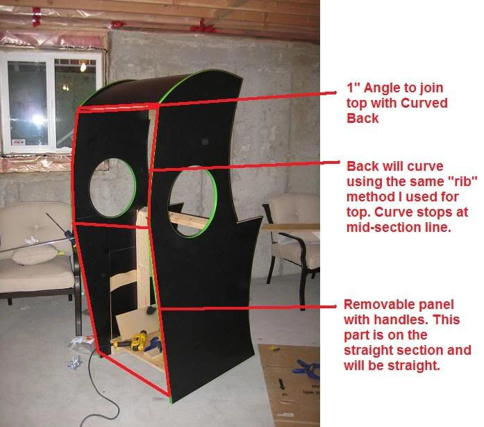
Curved back is going to look fantastic. It is being done in 3 stages…a first 1” piece will connect top of curve to middle curve. This is required as there is a steep angle of about 1“ before the software curve that extends to the midway point. I will do the midway softer curve using the same rib method I used for the top of the cab. The bottom panel will be a removable access panel that will be straight.
Here is a paint sketch that summarizes how I will do it:
If you look at the previous page it shows some closeups of the angled brackets I used. Here in a bit more verbal detail is what I did:
I have the bezel resting along the via monitor but pressure rests on the brackets. It touches the sides of the glass but rests on weather stripping I have put on the back of the bezel. Weather stripping is adhesive on one side with a peel away layer…the other side is black foam. I used the 1.5“ wide stuff. It is approximately 1/4” deep and can be purchased at Home Depot.
The top of the bezel passes up and behind the speaker panel by about 1.5“ where it does touch the glass it rests on 2 small angled iron brackets (1 on each side). The bottom sits on a 90 degree angle…the angle has about 3/4” of space on each edge…the bezel is 1/2“ which leave 1/4”. The glass I use is 22 1/4“ (top to bottom) and 26.5” (wide) by 1/4“ thick it rests perfectly on the angle (as you can see in the picture, it rests flush). The glass extends up to just below the speaker shelf (just touching it).
The angled wood is itself mounted at an angle to hold the bezel and glass by two 90 degree steel braces. These braces have holes in them which I use to insert pins. Gravity holds the glass and bezel in place but the pins ensure they stay put “Just in case”.
Let me know if you have any more questions…oh and the reason I have built it this way is that I can take everything apart quickly to get at the monitor etc.
I'll take a few more pictures if you like of the bezel. The other thing I have done on a previous cab is used angle brackets along the side of the monitor to rest the bezel on.
Page 11
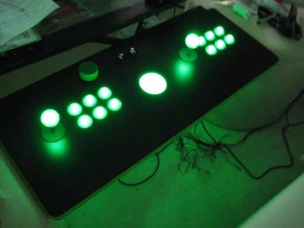
Finally got the lighting and wiring all done up in the cab. Here are some pics and a movie of the lighting. Im going to post a few so if you aren't in to pics scroll quick ;)
The marquee looks washed out…I can assure you in person it is not…the letters are all legible…maybe the movie will show it better after the pics:


And of course ye obligatory cheesy smiling proud papa photo:
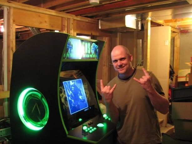
After this picture my wife reminded me that the basement won't build itself…was that a hint!?
Going to still see about lighting just the crevasse on the side art and of course the spinner…it already has UV paint on it but not sure where I would put a UV Light so will look at some earlier lighting suggestions for the spinner. First things first, finish the back off so I can close it up tight and roll it into its final carpeted spot in the basement.
Short Movie Clip showing lighting…again marquee and lights in general are not washed out, they appear slightly overexposed on this clip and in the pics…I have one LED tube in there turned around facing the foil:
Page 12
Q&A:
For the speaker sandwich basically you cut out a piece of plexi glass that covers the inside of the circle. I used a 16” x 16“ square cut of plexi glass. You place this plexi behind the neon speaker ring. The next layer is your artwork. The artwork is also 16” x 16“. The 3rd layer is a piece of hardboard that I also cut 16” x 16“. You then screw all the layers through the screw holes on the neon speaker ring into the inside of the cab.
The only thing I will be modifying is that I will be adding a small slit into the back of the hardboard to backlight the crevasse. I got lazy this past long weekend and only played..no building.
For volume I borrowed liberally, this time from Martijn's excellent SF cab. I used a 2.1 Logitech Z313 set. I just extended the volume and headphone as he did (although I haven't mounted them permanently inside the buttons yet. I didn't hack anything just extended what was already there as the volume dial fits in the button np as does the headphone jack. [[http://forum.arcadecontrols.com/index.php/topic,84649.0l.html|Martijn's SF Cab]
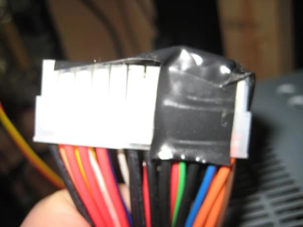
For those asking, here are a few pictures showing the PC Power Supply hack in a bit more detail. As mentioned I have a 2nd PC power supply hacked to not require it to be plugged in to a motherboard (also great for using as a test PS btw). The way to do this is as follows:
1) Find the green wire on your Power Supply Mobo connector cable. It should be pin 4. Once you locate it you just need to short it to one of the black cables on either side. I used 18 guage solid non-stranded and just made a small U:
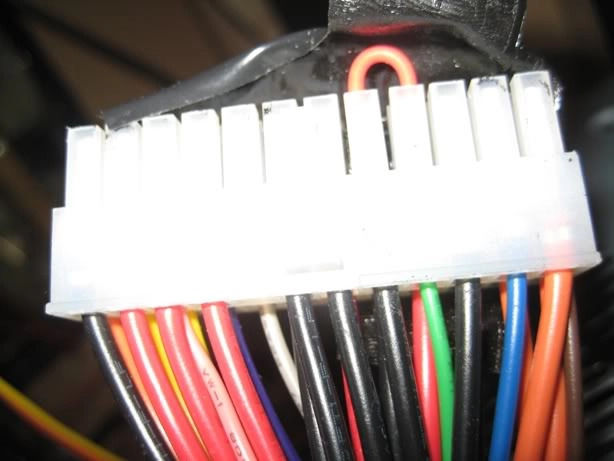
2) Then tape it up to prevent it from coming out. This is more for formality than function. If you are using 18 guage it won't easily slip out as the fit is tight…but for peace of mind…
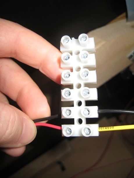
3) For drawing power to various devices like the LEDWiz or the Neon speaker rings I use Euro style terminal strips (type you screw to tighten not spade connectors). You can get these from Radio Shack/The Source (Canada). Or anywhere in Europe ;)
As mentioned the Neon speaker rings uses 12v. It carries those 12v through a red cable and ground through a black one. I connected those to the terminal strip and then ran the power supply 12v (yellow) and ground (black) into the other side of the terminal strip. You can cut these terminal blocks in between which I haven't done yet but will so its just the two hanging there.
If you were running to a 5v devices like some LEDs etc then you would just run the 5v on your LED to the strip and on the opposing side the PS's red 5v cable. Here is how mine looks 12v to 12v:
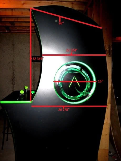
I have had a few people PM me for measurements. I finally got around to taking the measurements as the original cab was built with only overall height and width as a known variable and the rest was just improvised from Ond's render.
Some misc facts about the measurements before I list all them.
- The curved roof and back can't really be measured, just follow the curve at the top and around back by 1/4”. That is what I did.
- The Marquee actual size is 26.5“ x 8.5”. The Measurements shown are from top of top retainer to bottom of bottom retainer.
- Bezel is 26.5“ and 25” top to bottom but runs flush behind speaker shelf at the top and CP at the bottom.
- Bezel glass is 26.5“ x 22.5” and rests just below CP out of sight and rests flush with speaker shelf at top.
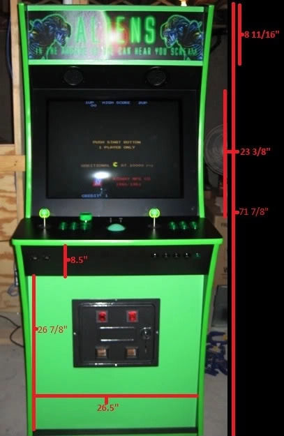
- Cab is 71 7/8“ from ground including the wheels…the wheels take up 1 1/8” of that height so actual cab height without wheels is 70 6/8“
- Top of CP with wheels on cab is at ~40” from the ground. This works out fine for me and my friends…your results may vary ;)
Here are the measurements:
Front:
CP/Bezel:
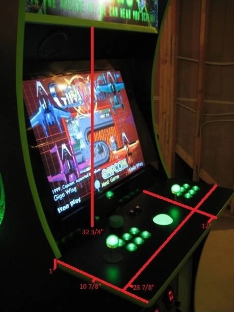
Top Side:
Bottom Side:
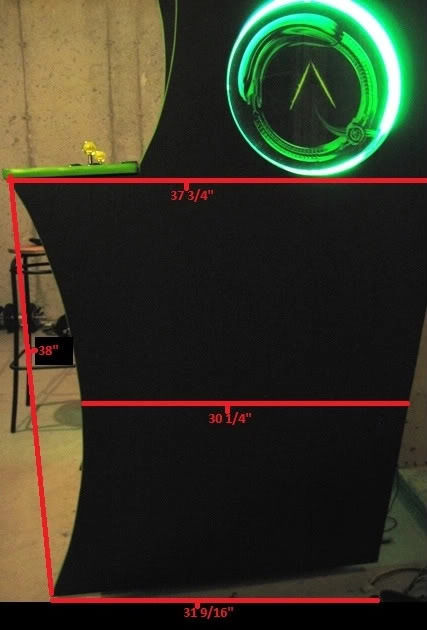
And that's it for now!